ATSAMC21N从寄存器开发到ASF、FreeRTOS裁剪移植、与AD7779评估版进行SPI通信获取AD数据采集
项目需求(后补)器件选型(后补)软件设计AtmelStudio环境下的ATSAMC21N开发配置打开Atmel studio,用usb线把开发板连接至PC,Windows10自动安装驱动,然后在Atmel studio上面会弹出板子的信息:上面有关于此板子的信息,asf开发文档,板子开发文档等都在里面。新建项目,此配置参考Atmel的配置视频。输入名字后进入选择界面,选择对应...
目录
声明
如若转载,请附转载地址并声明原作者。此项目在GitHub托管,所有的资料包括datasheet都在GitHub托管,托管地址。作者还拥有个人公众号,会写一些感悟文章,知圈,二维码如下,欢迎扫描关注:
说明
本项目分AD采集模块和软件模块。本文为软件模块,AD采集的硬件模块请参考该文章。
项目需求
一秒一千次采样以上,30通道以上,24bit以上分辨率。
器件选型
备选: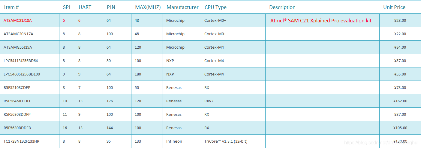
最终决定:ATSAMC21J18A
并购入了官方的该芯片的demo板: Atmel® SAM C21 Xplained Pro evaluation kit
软件配置与框架搭建
AtmelStudio环境下的ATSAMC21N开发配置
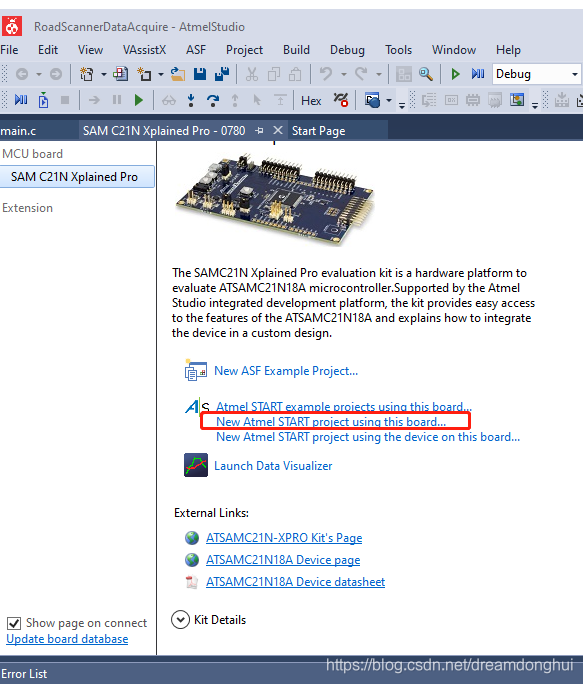
打开Atmel studio,用usb线把开发板连接至PC,Windows10自动安装驱动,然后在Atmel studio上面会弹出板子的信息: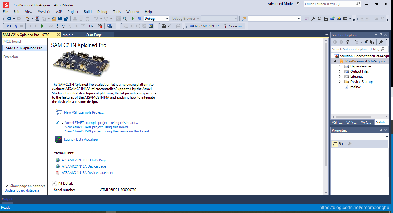
上面有关于此板子的信息,asf开发文档,板子开发文档等都在里面。
新建项目,此配置参考Atmel的配置视频。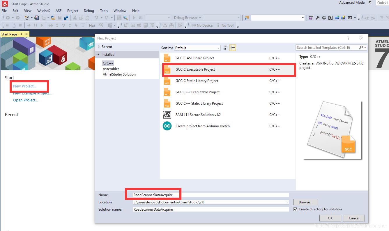
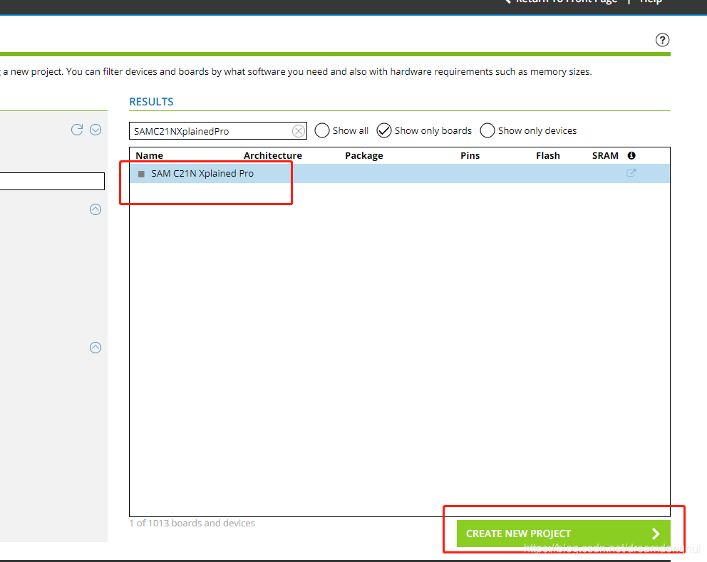
输入名字后进入选择界面,选择对应的MCU。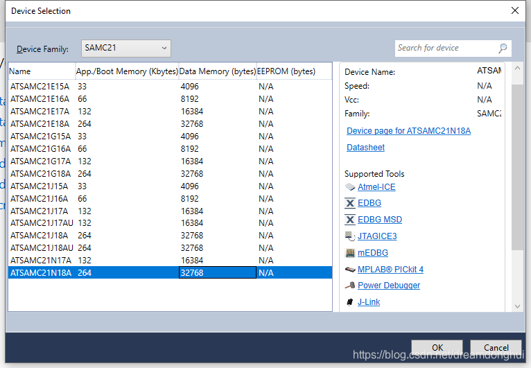
生成后的main.c文件如下所示:
/*
 * RoadScannerDataAcquire.c
 *
 * Created: 2019-12-18 15:18:10
 * Author : lenovo
 */


#include "sam.h"


int main(void)
{
    /* Initialize the SAM system */
    SystemInit();

    /* Replace with your application code */
    while (1)
    {
    }
}
为了熟悉板子,本例用寄存器原始方式、ASF框架、Freertos三种开发形式上都进行实验。保险起见,先把代码上传至Github。
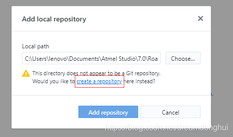
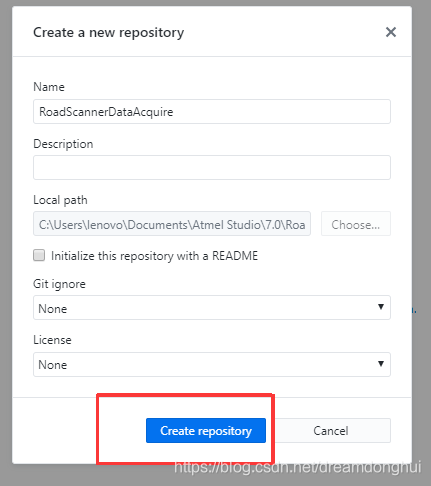
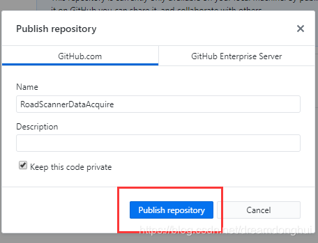
创建Github
打开Github,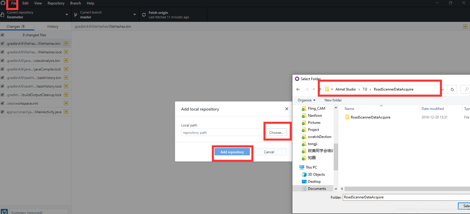
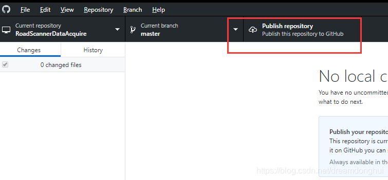
publish 到云端账号
寄存器方式(without ASF)
经查找SAM C21 Xplained Pro board的user guide,板子上有一个LED灯连接在PC的05脚上。本例用更改寄存器的方式实现对此灯的控制。
通过查看芯片的datasheet,找到以下两个需要更改的寄存器。
端口设置为输出: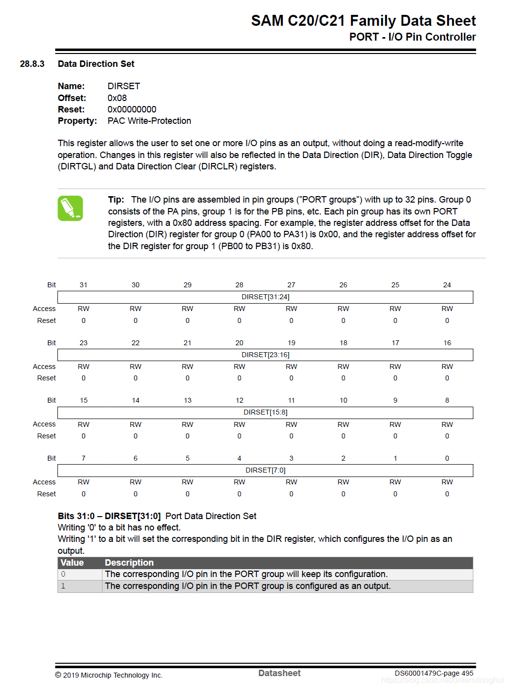
输出设置为低电平: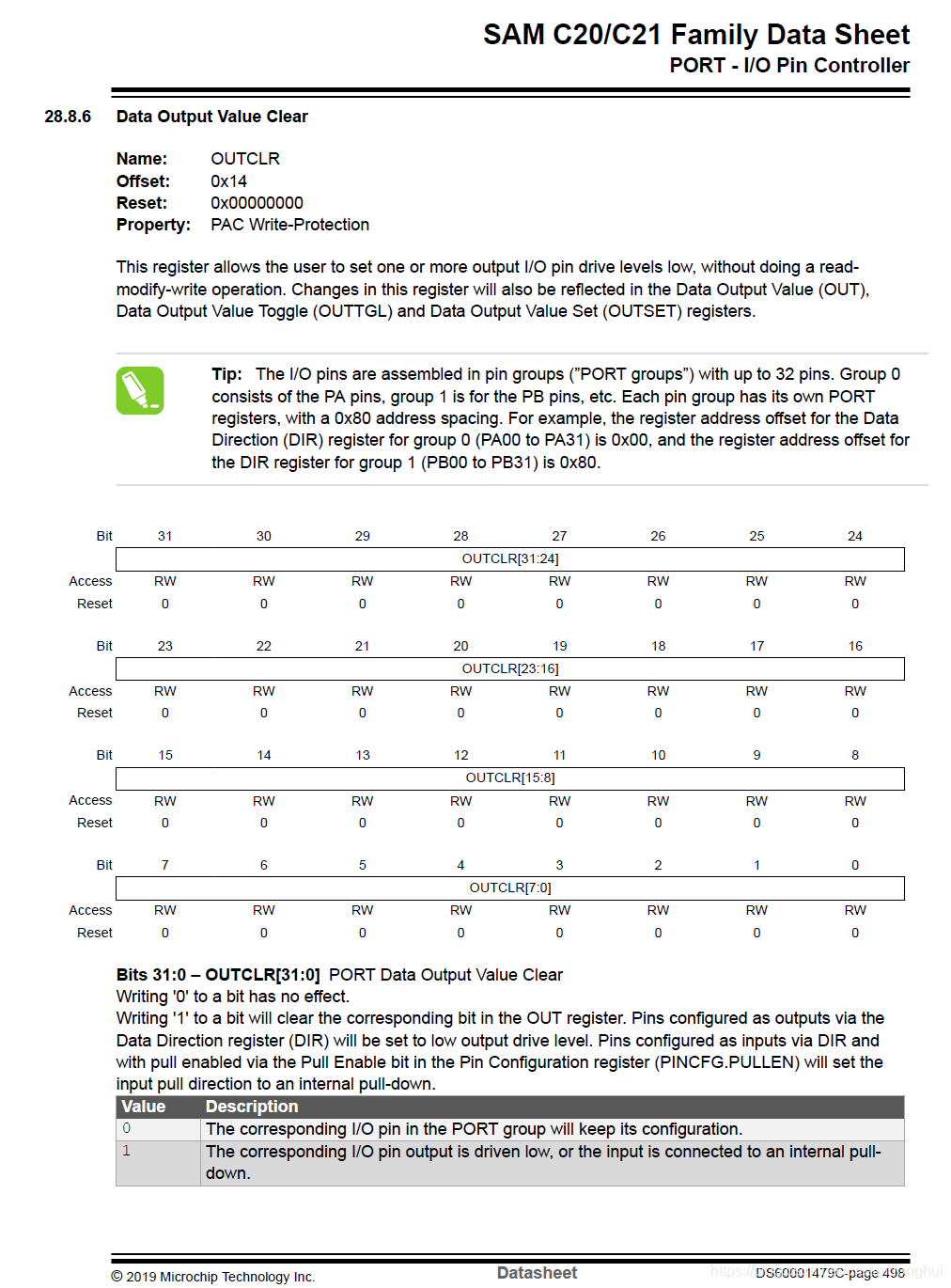
更改main函数:
int main(void)
{
    /* Initialize the SAM system */
    SystemInit();


    /* Replace with your application code */
	//将所有的PC口设置为输出。
	REG_PORT_DIRSET2 = 0xffffffff;
	//将所有的PC口置为低电平以点亮LED。(LED另一端为3.3V)
	REG_PORT_OUTCLR2 = 0xffffffff;
    while (1)
    {

    }
}
后来在官网找到了兄弟板的示例程序。并根据示例程序根据开发板做了更改,现在板子的LED在PC05脚,而示例程序的引脚在PA15脚。加载程序后LED以1hz的频率闪烁。
#include "sam.h"
// I/O Ports definitions
#define PORTA     (0ul)
#define PORTB     (1ul)
#define PORTC     (2ul)

// LED0 definitions
#define LED0_PORT            PORTC
#define LED0_PIN_NUMBER      (05ul)
#define LED0_PIN             PORT_PC05
/** VARIABLES *****************************************************************/

static uint32_t ul_tickcount=0 ;	// Global state variable for tick count

/** LOCAL PROTOTYPES **********************************************************/

void AppInit(void);					// Application Hardware/Software Initialization

/** main() ********************************************************************/

int main(void){

	/* Initialize the SAM system - auto-generated code */
    SystemInit();

	/* Application hardware and software initialization */
	AppInit();

    /* Replace with your application code */
    while(1){
	__NOP();
    }
}

/*******************************************************************************
 * Function:        void AppInit(void)
 *
 * PreCondition:    None
 *
 * Input:           None
 *
 * Output:          None
 *
 * Side Effects:    None
 *
 * Overview:        This routine takes care of all of the hardware/software
 *                  initialization that is required.
 *
 * Note:
 *
 ******************************************************************************/
void AppInit(void){

	/*	Clock initialization (CPU, AHB, APBx)
		The System RC Oscillator (RCSYS) provides the source for the main clock
		at chip startup. It is set to 4 MHz.

		Add code here to change the system clock
	*/

	// Assign the LED0 pin as OUTPUT
	PORT->Group[LED0_PORT].DIRSET.reg = LED0_PIN ;
	// Set the LED0 pin level, i.e. put to 3.3V -> this turns off the LED
	PORT->Group[LED0_PORT].OUTSET.reg = LED0_PIN ;

	// Configure SysTick to trigger every millisecond using the CPU Clock
	SysTick->CTRL = 0;					// Disable SysTick
	SysTick->LOAD = 3999UL;				// Set reload register for 1mS interrupts
	NVIC_SetPriority(SysTick_IRQn, 3);	// Set interrupt priority to least urgency
	SysTick->VAL = 0;					// Reset the SysTick counter value
	SysTick->CTRL = 0x00000007;			// Enable SysTick, Enable SysTick Exceptions, Use CPU Clock
	NVIC_EnableIRQ(SysTick_IRQn);		// Enable SysTick Interrupt

}

/*******************************************************************************
 * Function:        void SysTick_Handler(void)
 *
 * PreCondition:    None
 *
 * Input:           None
 *
 * Output:          None
 *
 * Side Effects:    None
 *
 * Overview:        This interrupt handler is called on SysTick timer underflow
 *
 * Note:
 *
 ******************************************************************************/
void SysTick_Handler(void){

	ul_tickcount++ ;
	// Toggle LEDs every second (i.e. 1000ms)
	if(ul_tickcount % 1000 == 0){
		// Toggle LED pin output level.
		PORT->Group[LED0_PORT].OUTTGL.reg = LED0_PIN ;
	}
}
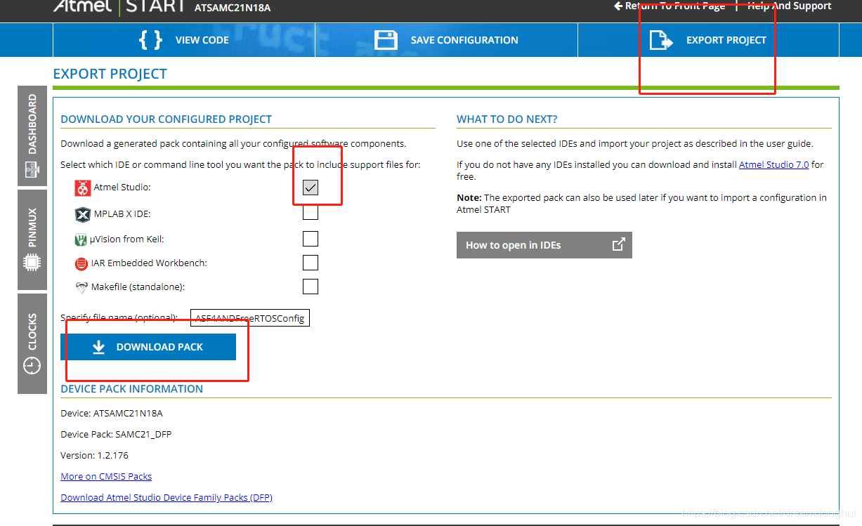
ASF
阅读了官方的说明后,ASF4必须用Atmel START在线工具来配置。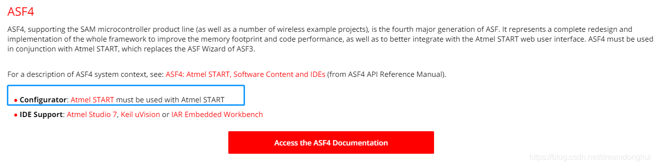
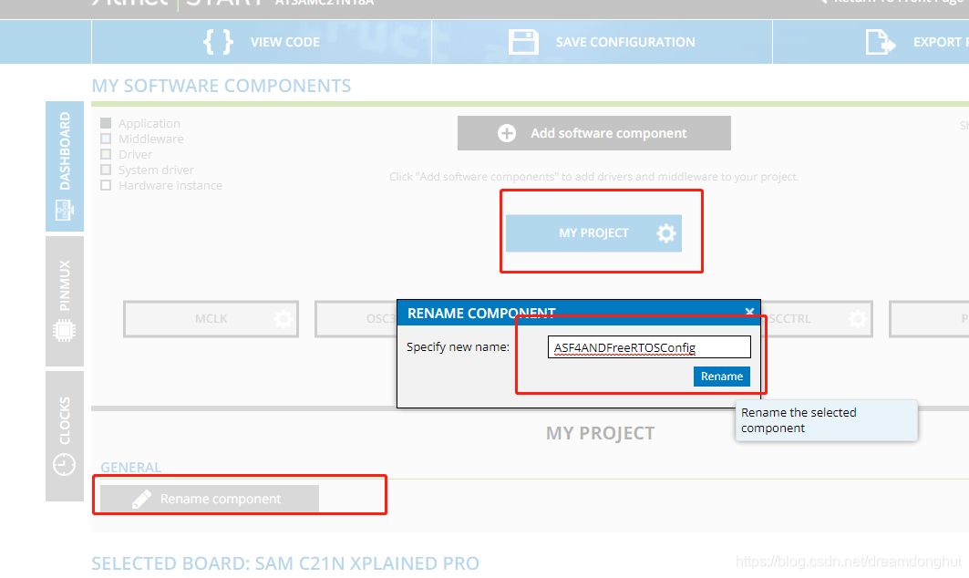
添加完后改下名字,最后如下所示: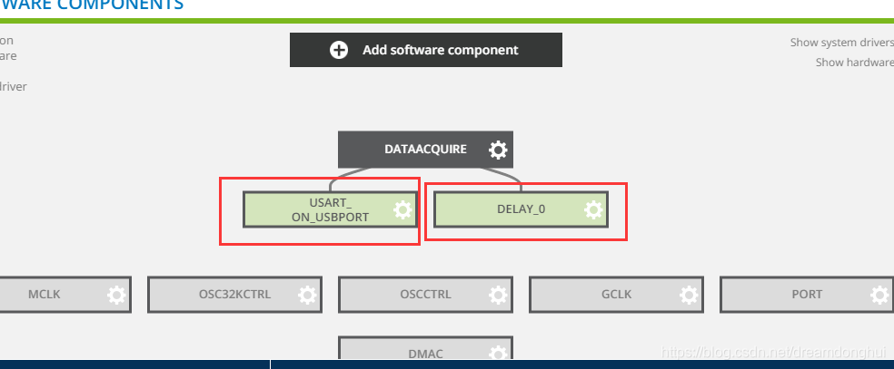
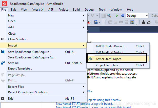
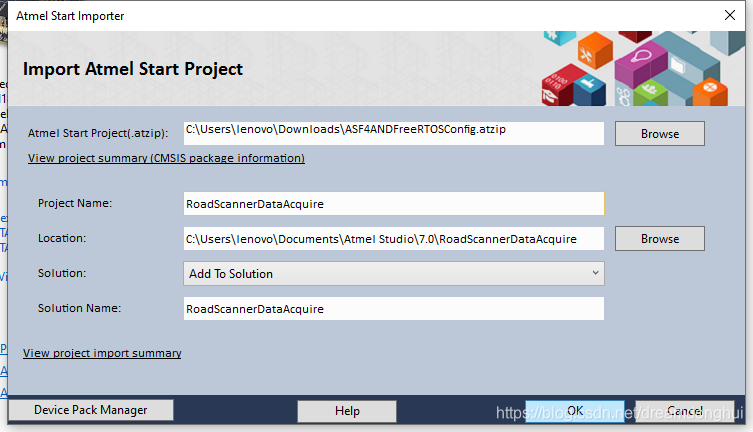
由于之前solution里面已经有RoadScannerDataAcquire的project,所示创建失败,由于之前Github已经配置好了,并不想重新配置,也不想改名,所以在Atmel studio 7里面右击project名字,点击remove,删除,记得要去在计算机端删掉文件夹,否则之前的文件会干扰新文件的生成,造成未知的错误,然后再用原名称导入就可以了。
创建完后打开,发现直接用板子上的USB下载口可以进行uart调试。查看手册后发现引脚为TX:PB10、 RX:PB11。
在Atmel Studio里面选择reconfigure,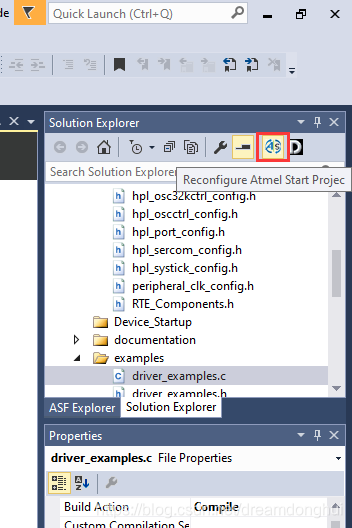
打开后找到如下配置,更改引脚。发现驱动用的是同步的,也改为异步。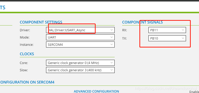
更改时发现这两个引脚PB11和PB10已经被SPI3给占了,先去SPI配置里面把这两个口改为其它引脚,把这两个口空出来,然后再返回UART里面设置这两个口。
设置完成并重新生成后,找到生成的文件下的示例代码并打开,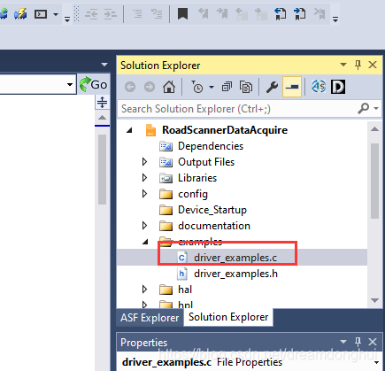
打开后找到如下代码块:
/**
 * Example of using USART_3 to write "Hello World" using the IO abstraction.
 */
void USART_3_example(void)
{
	struct io_descriptor *io;
	usart_sync_get_io_descriptor(&USART_3, &io);
	usart_sync_enable(&USART_3);

	io_write(io, (uint8_t *)"Hello World!", 12);
}
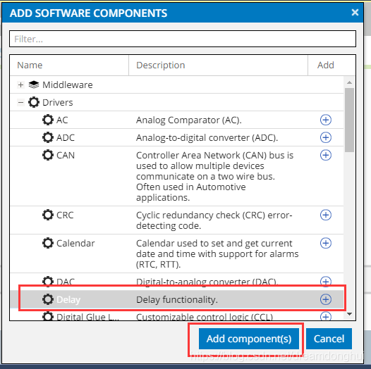
因为还会用到delay函数,同文件里面找到delay的示例代码:
void delay_example(void)
{
	delay_ms(5000);
}
打开main.c,里面生成的代码如下:
#include <atmel_start.h>
int main(void)
{
	/* Initializes MCU, drivers and middleware */
	atmel_start_init();

	/* Replace with your application code */
	while (1) {
	}
}
根据示例程序,将main.c改为如下:
#include <atmel_start.h>
#include <driver_examples.h>

int main(void)
{
	/* Initializes MCU, drivers and middleware */
	atmel_start_init();

	/* Replace with your application code */
	while (1) {
	USART_On_USBPort_example();
	delay_ms(1000);
	}
}
编译并将代码下载到板子。
前面改了uart的引脚号,为的就是直接使用Atmel Studio里面的Data Visualizer功能直接进行虚拟串口的调试。
打开data visualizer工具: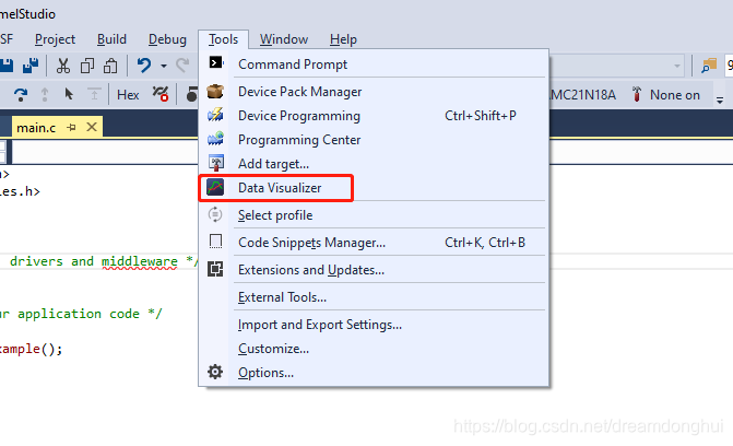
双击serial port: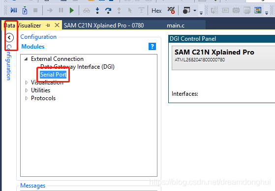
设置: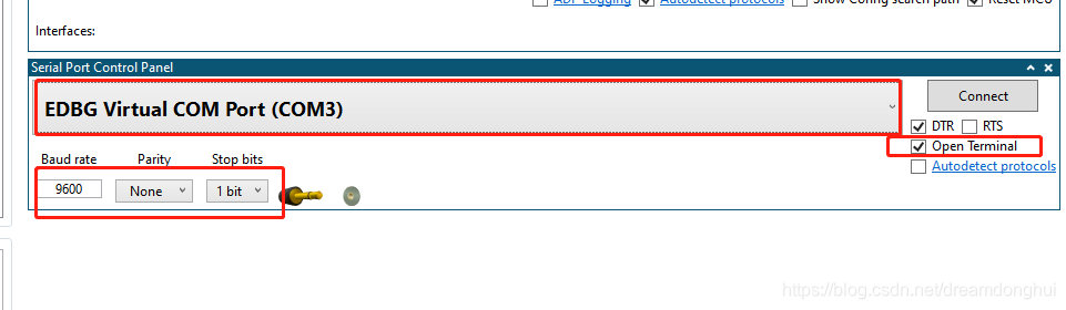
点击上面的connect,会弹出terminal终端,然后我们的板子会按照我们之前设计的每秒发送一次hello word。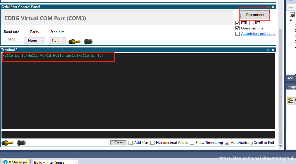
ASF4的测试代码到此结束。
FreeRTOS
再次打开配置: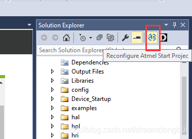
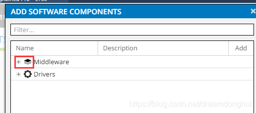
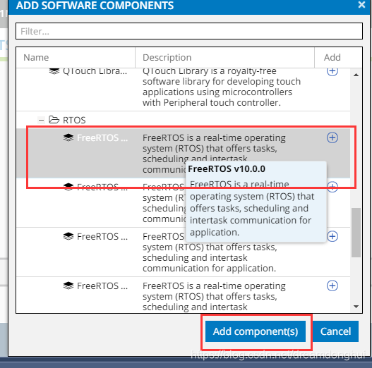
点击下能看到配置: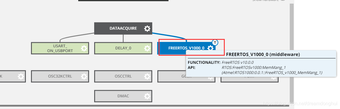
点击freertos后,会出现其配置选项,在这里用默认的即可。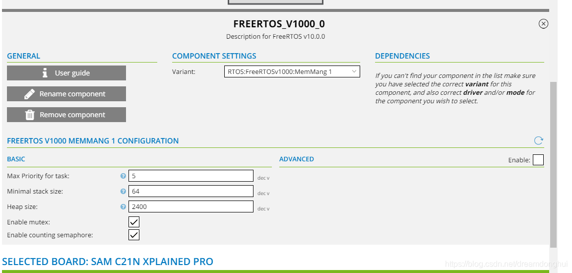
点击生成: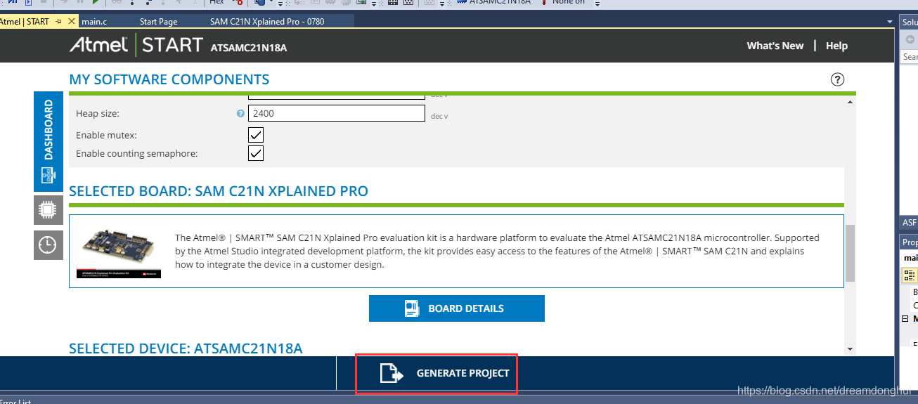
生成后找到如下rtos的示例代码: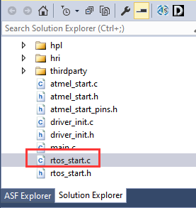
打开后代码如下:
/*
 * Code generated from Atmel Start.
 *
 * This file will be overwritten when reconfiguring your Atmel Start project.
 * Please copy examples or other code you want to keep to a separate file or main.c
 * to avoid loosing it when reconfiguring.
 */
#include "atmel_start.h"
#include "rtos_start.h"
#include "driver_examples.h"

#define TASK_EXAMPLE_STACK_SIZE (128 / sizeof(portSTACK_TYPE))
#define TASK_EXAMPLE_STACK_PRIORITY (tskIDLE_PRIORITY + 1)
static TaskHandle_t      xCreatedExampleTask;
static SemaphoreHandle_t disp_mutex;

/**
 * OS example task
 *
 * \param[in] p The void pointer for OS task Standard model.
 *
 */
static void example_task(void *p)
{
	(void)p;
	while (1) {
		if (xSemaphoreTake(disp_mutex, ~0)) {
			/* add your code */
			xSemaphoreGive(disp_mutex);
		}
		os_sleep(500);
	}
}

/*
 * Example
 */
void FREERTOS_V1000_0_example(void)
{
	disp_mutex = xSemaphoreCreateMutex();

	if (disp_mutex == NULL) {
		while (1) {
			;
		}
	}

	if (xTaskCreate(
	        example_task, "Example", TASK_EXAMPLE_STACK_SIZE, NULL, TASK_EXAMPLE_STACK_PRIORITY, xCreatedExampleTask)
	    != pdPASS) {
		while (1) {
			;
		}
	}

	vTaskStartScheduler();

	return;
}
上面的代码简单明了。在main里面调用下,FreeRTOS就启动了。在main函数里面添加调用,添加了两句,一句是为了调用示例函数添加的#include “rtos_start.h”,另一句是调用函数FREERTOS_V1000_0_example(); 添加完这两句后,原先main里面的while死循环就永远不会执行到了,任务由FreeRTOS调度。
如下所示:
#include <atmel_start.h>
#include <driver_examples.h>
#include "rtos_start.h"

int main(void)
{
	/* Initializes MCU, drivers and middleware */
	atmel_start_init();
	FREERTOS_V1000_0_example();

	/* Replace with your application code */
	while (1) {
	USART_On_USBPort_example();
	delay_ms(1000);
	}
}
返回rtos_start.c函数,添加#include "driver_examples.h"已引用我们前面的uart测试函数。然后在示例任务中加入串口调用函数,如下:
/**
 * OS example task
 *
 * \param[in] p The void pointer for OS task Standard model.
 *
 */
static void example_task(void *p)
{
	(void)p;
	while (1) {
		if (xSemaphoreTake(disp_mutex, ~0)) {
			/* add your code */
				USART_On_USBPort_example();
//				delay_ms(1000);
			xSemaphoreGive(disp_mutex);
		}
		os_sleep(500);
	}
}
运行后500ms输出一次hello word。运行结果如下: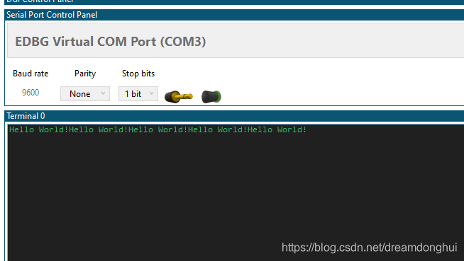
与AD7779评估版进行SPI通信获取AD数据采集
ANALOG DEVICES提供官方的C语言裸机驱动,给开发带来了极大的便利,全资源可以点击此处阅读原文。
AD7779评估版配置
评估版配置比较繁琐,配置过程的说明篇幅很长,作者专门写了一篇文章记录,请参见此处。
SPI通信模块添加与配置
再次点击配置: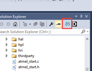
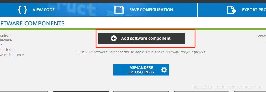
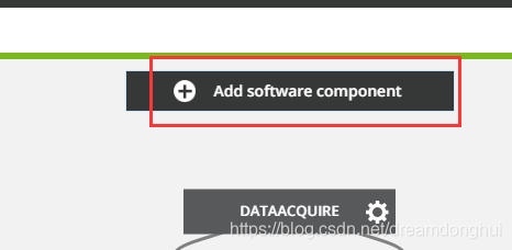
点击添加部件: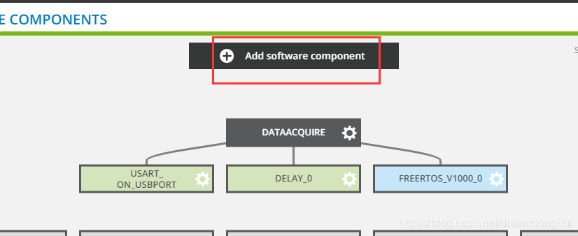
找到Drivers: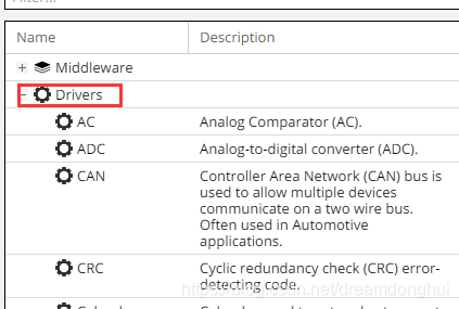
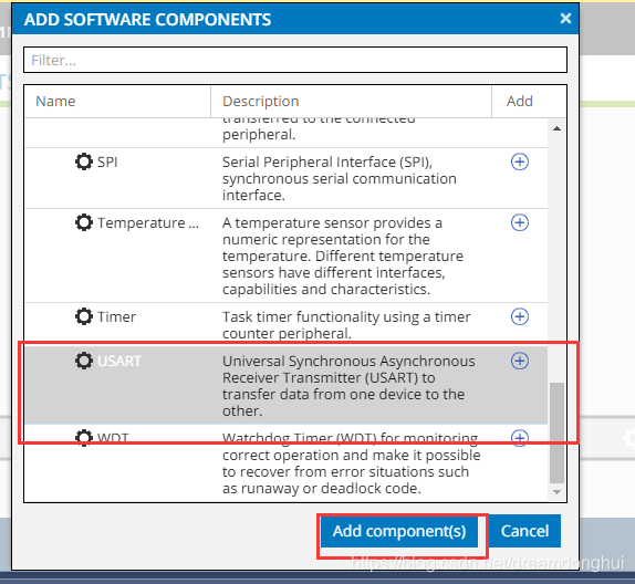
找到SPI并添加: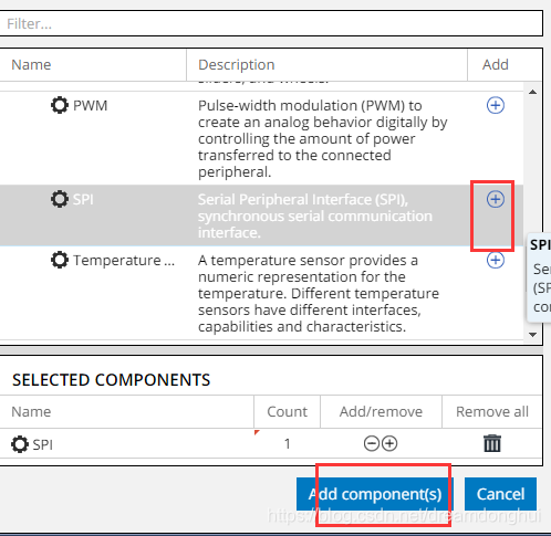
返回选中刚才添加的SPI: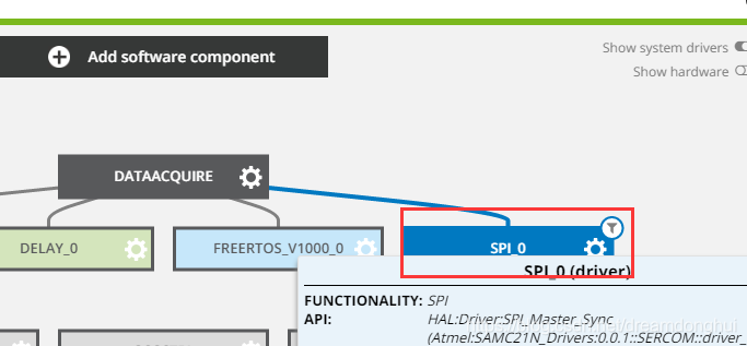
点击后展开配置选项,然而第一个关于Driver的驱动配置就有近十个,如下: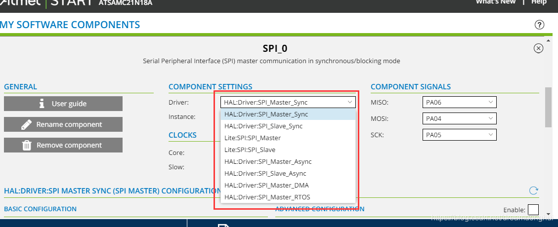
经搜索,终于在官网上找到其各个不同driver的描述。此描述在官网有PDF版本的文档,文档名字:ASF4 API Reference Manual。
根据开发板手册,选用EXT3端口上的脚: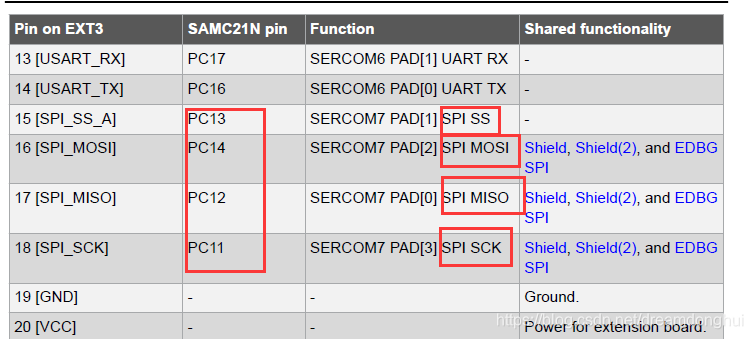
引脚改为: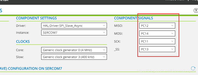
时序也需要设置,经翻看文档,AD7779的DOUT模式时序图如下: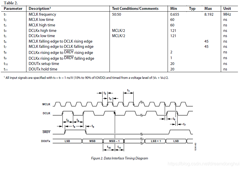
SPI时序模式如下: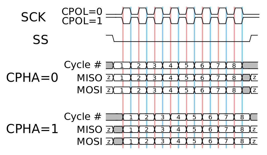
由以上信息,配置SPI参数为: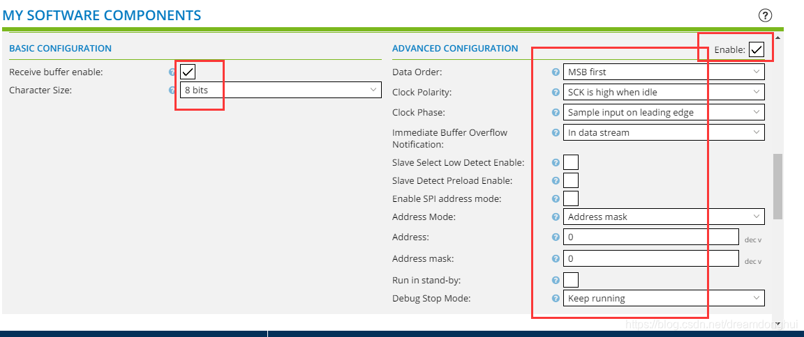
再次点击生成项目: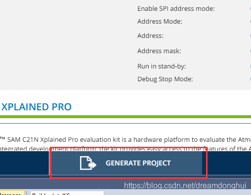
代码结构分拆重构
前面测试的过程中,不断通过Atmel START进行配置添加/更改。每次都需要重新生成代码,生成代码的时候会对很多文件进行覆盖,个人在自动生成的文件上做的更改会被覆盖掉。需要每个核对。
由于后续会对文件进行频繁的更改等,为从敏捷角度出发,避免不必要的麻烦,现对源代码进行分拆,分拆后只对main.c在源码中进行更改(因其名字的不可改变性)。
分拆后的原则:
- 将main.c的代码代码更改量尽可能的精简。
- 将所有用到的需要更改的全部摘出。
- 敏捷化。
分拆后的代码示例:
#include <atmel_start.h>
#include <driver_examples.h>
#include "Hui_rtos_start.h"

int main(void)
{
	/* Initializes MCU, drivers and middleware */
	atmel_start_init();
	Hui_FREERTOS_V1000_0_example();

	/* Replace with your application code */
	while (1) {
// Since we added the FreeRTOS system to manage the task, this loop will never be executed.
	}
}
/*
 * Hui_USBPort.c
 *
 * Created: 2020-05-13 14:06:50
 *  Author: TomorrowNeverComes
 */

#include "driver_init.h"
#include "utils.h"
#include "Hui_USBPort.h"
/**
 * Example of using USART_On_USBPort to write "Hello World" using the IO abstraction.
 *
 * Since the driver is asynchronous we need to use statically allocated memory for string
 * because driver initiates transfer and then returns before the transmission is completed.
 *
 * Once transfer has been completed the tx_cb function will be called.
 */

static void tx_cb_USART_On_USBPort(const struct usart_async_descriptor *const io_descr)
{
	/* Transfer completed */
}

void USART_On_USBPort_Output(uint8_t Data_USART_On_USBPort[], uint8_t arry_size)
{
	struct io_descriptor *io;

	usart_async_register_callback(&USART_On_USBPort, USART_ASYNC_TXC_CB, tx_cb_USART_On_USBPort);
	/*usart_async_register_callback(&USART_On_USBPort, USART_ASYNC_RXC_CB, rx_cb);
	usart_async_register_callback(&USART_On_USBPort, USART_ASYNC_ERROR_CB, err_cb);*/
	usart_async_get_io_descriptor(&USART_On_USBPort, &io);
	usart_async_enable(&USART_On_USBPort);

	io_write(io, Data_USART_On_USBPort, arry_size);
}
/*
 * Hui_USBPort.h
 *
 * Created: 2020-05-13 14:08:45
 *  Author: TomorrowNeverComes
 */


#ifndef HUI_USBPORT_H_
#define HUI_USBPORT_H_

#ifdef __cplusplus
extern "C" {
	#endif /* __cplusplus */

void USART_On_USBPort_Output(uint8_t*, uint8_t);

	#ifdef __cplusplus
}
#endif

#endif /* HUI_USBPORT_H_ */
/*
 * Hui_rtos_start.c
 *
 * Created: 2020-05-13 10:28:05
 *  Author: TomorrowNeverComes
 */
#include "atmel_start.h"
#include "Hui_rtos_start.h"
#include "Hui_USBPort.h"

#define TASK_EXAMPLE_STACK_SIZE (128 / sizeof(portSTACK_TYPE))
#define TASK_EXAMPLE_STACK_PRIORITY (tskIDLE_PRIORITY + 1)
static TaskHandle_t      xCreatedExampleTask;
static SemaphoreHandle_t disp_mutex;

/**
 * OS example task
 *
 * \param[in] p The void pointer for OS task Standard model.
 *
 */
static void example_task(void *p)
{
	(void)p;
	while (1) {
		if (xSemaphoreTake(disp_mutex, ~0)) {
			/* add your code */
			static uint8_t example_USART_On_USBPort[ ] = "He00000o World!";
				USART_On_USBPort_Output(example_USART_On_USBPort,sizeof(example_USART_On_USBPort)/sizeof(uint8_t));
//				delay_ms(1000);
			xSemaphoreGive(disp_mutex);
		}
		os_sleep(500);
	}
}

/*
 * Example
 */
void Hui_FREERTOS_V1000_0_example(void)
{
	disp_mutex = xSemaphoreCreateMutex();

	if (disp_mutex == NULL) {
		while (1) {
			;
		}
	}

	if (xTaskCreate(
	        example_task, "Example", TASK_EXAMPLE_STACK_SIZE, NULL, TASK_EXAMPLE_STACK_PRIORITY, xCreatedExampleTask)
	    != pdPASS) {
		while (1) {
			;
		}
	}

	vTaskStartScheduler();

	return;
}
/*
 * Hui_rtos_start.h
 *
 * Created: 2020-05-13 10:42:30
 *  Author: TomorrowNeverComes
 */


#ifndef HUI_RTOS_START_H_
#define HUI_RTOS_START_H_


#ifdef __cplusplus
extern "C" {
	#endif /* __cplusplus */

	#include <FreeRTOS.h>
	#include <task.h>
	#include <semphr.h>
	#include <hal_rtos.h>

	void Hui_FREERTOS_V1000_0_example(void);

	#ifdef __cplusplus
}
#endif /* __cplusplus */


#endif /* HUI_RTOS_START_H_ */
SPI代码测试
未完,作者已离职,此项目不再维护。

魔乐社区(Modelers.cn) 是一个中立、公益的人工智能社区,提供人工智能工具、模型、数据的托管、展示与应用协同服务,为人工智能开发及爱好者搭建开放的学习交流平台。社区通过理事会方式运作,由全产业链共同建设、共同运营、共同享有,推动国产AI生态繁荣发展。
更多推荐


 4
4 0
0- 0


 已为社区贡献1条内容

所有评论(0)